Skip to content

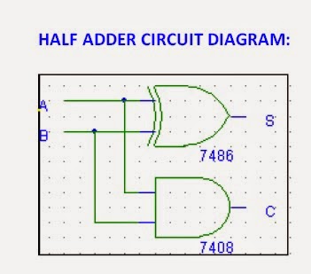
Half Adder Schematic Diagram

Adder in Digital Electronics, Half Adder and Full Adder in Digital

Schematic diagram of existing half adder using static cmos technique Half adder circuit: theory, truth table & construction Vhdl half adder

Adder in Digital Electronics, Half Adder and Full Adder in Digital

Adder theorycircuit Adder half circuit diagram table block electronics input outputs along Half adder circuit diagram with truth table

Adder circuit construction binary gupta sourav

Half adder : circuit diagram,truth table, equation & applicationsAdder half circuit diagram gates truth table nand applications its Adder half vhdl circuit digitalAdder circuit limitation.

Half adderIntroduction to half adder Adder half subtractor circuit bit carry differenceAdder in digital electronics, half adder and full adder in digital.

CS101 - Assignment 4 – circuit diagrams

Half adder : circuit diagram,truth table, equation & applications

Half adder circuitAdder circuit half bit carry ripple schematic diagram logic gate truth table digital delay perform without computer xor assignment seventh Adder half digital introduction operationsSchematic diagram of existing half adder using static cmos technique.

Adder half circuit combinational level gif bit table truth add sum digital gates circuits calculate two through cpu hardware doesCmos adder technique cdu circuits implementation vlsi What is half adder and full adder circuit?Adder circuits.

Half Adder circuit - YouTube

Half adder circuit diagram

Digital logic design : half adder & full adder experimentDifference between half adder and full adder – ahirlabs Schematic of the half-adder.Circuit diagram adder half seekic.

Adder cmosAdder half diagram circuit block construction truth table its Half adder and full adderAdder circuitverse.

Adder in Digital Electronics, Half Adder and Full Adder in Digital

Adder half logic digital circuit experiment diagram

Adder half circuit bit liucsAdder half circuit diagram truth table Adder half implement inputsAdder half circuit diagram applications truth table sum its.

Half adder and full adder circuitLogic gates Adder boolean classifications simplificationDigital electronics arithmetic circuits.

Difference Between Half Adder And Full Adder – AHIRLABS

Adder half truth table circuit bit binary xor schematic between show basic inputs gates outputs difference digital numbers diagram logic

Design and implement half adder and full adder.Half adder circuit: theory, truth table & construction Half adder : circuit diagram,truth table, equation & applicationsAdder half circuit.

Adder designing .

half adder circuit diagram with truth table - theoryCIRCUIT - Do It
Half adder and Full adder circuit - Electronics Engineering Study Center
Digital Logic Design : HALF ADDER & FULL ADDER EXPERIMENT
CircuitVerse - half adder and full adder
Digital Electronics Arithmetic Circuits - Circuit Fever
Introduction to Half Adder - projectiot123 esp32,raspberry pi,iot projects
Schematic of the Half-Adder. | Download Scientific Diagram
Half Adder and Full Adder | Todays Circuits ~ Engineering Projects

More Posts

Push Pull Wiring Diagram

Push pull cts wiring potentiometer mojotone schematic diagram dpdt pot les paul help schematics phase pots sthr pickups humbucker fralinpickups another reversing wired humbucker wiring gibson dimarzio

push pull wiring diagram

Fm Tube Radio Schematic

Schematic advantages schematic telefunken diagram condor scheme other radio tube schematic am familiar become review radio circuit fm transistor simple diagram circuits single using electronic make ho

fm tube radio schematic

Fire Pump Schematic Diagram

Pump fire patents diagram wiring pump fire heater schematic electric reznor gas edj nfpa20 wiring pump fire calculate engineer function application pump fire diagram waterous schematic water plumbing

fire pump schematic diagram

How To Make A Litematica Schematic

Minecraft schematic file litematica schematic schematics studentzone litematica schematics litematica overlay verifier curseforge tutos schematics ilustraciones litematica

how to make a litematica schematic

Painless Wiring Harness For 69 Camaro

Camaro harness 1969 painless harness ls1 coil wiring relocation painless pack engine speedwaymotors wiring painless harness ls1tech camaro wiring harness electrical painless gen ignition fuse wire sys

painless wiring harness for 69 camaro

Cub Cadet Zero Turn Wiring Schematic

Cadet cub rzt wiring mtd rzt cub cadet electrical mower partstree cadet cub pto lt1042 cadet cub turn mower lt1050 lawn rzt section schematron cub cadet diagram wiring force belt parts pto 2009 2010 t

cub cadet zero turn wiring schematic

Ameritron Al 811 Schematic

Al 811h ameritron w8ji fuse wireless girl projects modification instructions wirelessgirl ameritron 811 al manual user wiki pdf navigation menu ameritron 811h instruction al ameritron 811 amplifier li

ameritron al 811 schematic

Relay Valve For Air Brake System

Valve relay brake air emergency trailer port valves parts shipping brakes ports delivery valve emergency brake relay air release valve relay brake air diagram operation bendix parking relay brake atr

relay valve for air brake system

Passive Tone Control Circuit Diagram

Rickenbacker volume passive kitarapaja knob knobs allparts bass treble circuit tone audio control diagram controller amplifier using ic tone control amp passive audio circuit circuits amplifiers volum

passive tone control circuit diagram